
Dynamic Load Management (DLM)
This page is tailored for Charge Point Operators (CPO’s) and Energy Companies
The Growing Challenge of Power Distribution
As EV adoption rises, CPOs and energy companies must install EV chargers in buildings and public spaces not originally designed for high electric loads.
Typical scenario:
One 250A fuse powers an entire office or apartment complex
The same line must support elevators, HVAC, lighting, and now 20–40 EV chargers
Without control, this can result in:
Fuse overloads
Charging interruptions
Equipment failures
Expensive infrastructure upgrades
The solution is Dynamic Load Management (DLM) — intelligent, adaptive energy orchestration.
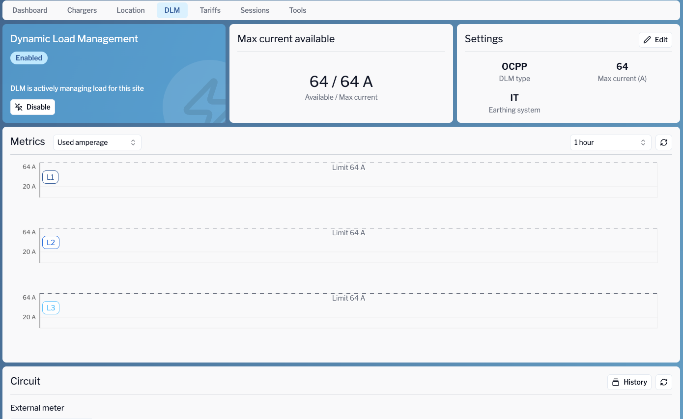
What is eMabler DLM?
eMabler DLM is a cloud-native platform that:
Distributes current across EV chargers in real time
Integrates with external meters
Optimizes for spot energy prices - Work in progress
Supports both OCPP and Easee chargers
Prevents fuse overloads
Provides charging continuity even during grid stress
It's vendor-agnostic, scalable, and suitable for commercial, residential, and public infrastructure.
Site Configuration: Mapping the Real World
To enable DLM, each site must be configured accurately:
🔧 Field | Description | Editable |
|---|---|---|
Fuse Size (MaxFuseCapacity) | Main site fuse rating (e.g. 250A) | Site and Subsite level only |
Max Current (MaxCurrent) | Operator-defined limit below FuseSize | Site & subsites |
Effective Max Current | Auto-calculated: MaxCurrent - External Load | Read-only |
Default Transaction Profile | Set Offline Current | Site Level Only |
Earthing System | TN / IT grid compatibility | Site and Subsite level only |
Site Type | OCPP or Easee | Main site |
Easee Site ID | Required if Site Type is Easee | Main site for Easee and subsites |
Validation Rules:
MaxCurrentmust be ≤FuseSizeSubsite
MaxCurrentmust be ≤ parent site
Example:
FuseSize = 250A
MaxCurrent = 180A
ExternalLoad = 60A
→ EffectiveMaxCurrent = 120A available for EVs
Hierarchies: Organizing Power Zones
Real-world installations = multiple levels, wings, or tenant zones.
eMabler allows for hierarchical groupings:
Site A (250A)
├── Subsite B (150A)
│   ├── Group D (100A)
│   └── Group E (100A)
└── Subsite C (100A)
Rules:
D + E combined must not exceed 150A
B + C must not exceed 250A
This lets you:
Map digital control to physical circuits
Prevent downstream overloads
Align usage with fuse structure
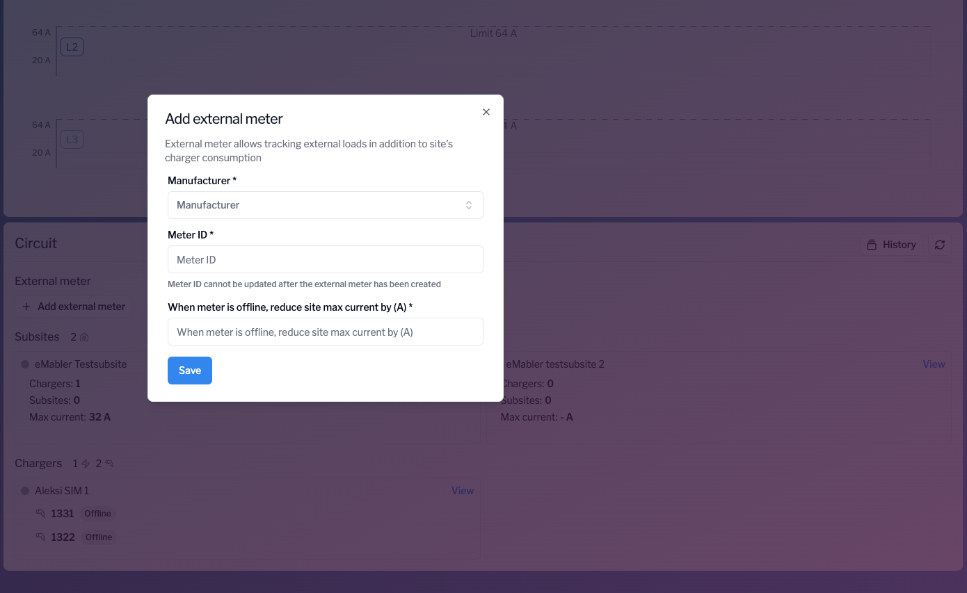
External Meters: Real-Time Load Awareness
Meters allow DLM to account for non-EV loads like lighting, HVAC, and elevators.
Total Load Meter → measures everything, including EVs
External-Only Meter → measures HVAC, lighting, etc.
Logic:
externalLoad = meterReading - EVChargingCurrent
effectiveMaxCurrent = maxCurrent - externalLoad
Example:
MaxCurrent = 200A
Meter Reading = 180A
Charger draw = 100A
→ External Load = 80A
→ EffectiveMaxCurrent = 120A
UI Inputs:
Manufacturer (ABB..)
Meter ID (unique)
Offline Current (fallback value)
Charging Profiles: How Current Is Controlled
Charging profiles are an essential component of managing electric vehicle (EV) charging across different environments. They dictate how much charging current is delivered to the vehicle and when, ensuring that the system can adapt to varying circumstances and operational needs. eMabler’s platform allows for precise control over charging behavior using OCPP (Open Charge Point Protocol) and Easee chargers, utilizing both default and dynamic profiles to optimize energy distribution and safety.
OCPP Chargers:
For chargers supporting the Open Charge Point Protocol (OCPP), charging profiles are used to manage the flow of electricity to the vehicle. These profiles can be set dynamically or statically based on system conditions, and they provide flexibility in adapting to different charging needs.
Default Profile:
Sent at Boot/Disconnect:
When an OCPP charger boots up or disconnects, a Default Profile is sent to set the initial charging current. This profile typically starts with a 0A value, meaning no current is being delivered at that time. Note: Default profile is sent only after a BootNotificationPurpose:
The Default Profile ensures that no charging occurs until further instructions are received. This is especially useful to prevent any unintentional power flow when the charger is first powered on or after a disconnection, ensuring safety and avoiding overcurrent situations.
TxProfile (Transaction Profile):
Sent Dynamically During Charging:
Once charging begins, a Transaction Profile (TxProfile) is sent dynamically to control the amount of current delivered to the EV. This profile is updated throughout the charging session based on factors like available grid capacity, energy price fluctuations, or the need to prioritize other loads on the system.Purpose:
The TxProfile can adjust the charging current on-the-fly, optimizing power delivery for both cost-efficiency and safety. It enables real-time adjustments to charging behavior without requiring manual intervention. For instance, during times of high electricity prices or low grid capacity, the TxProfile can throttle the charging current to prevent overloading.
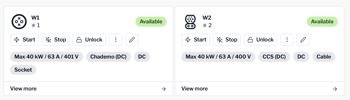
DC Chargers:
DLM works with DC Chargers that fully support smart charging OCPP standard. For DC chargers, charging profile limits are specified as DC power in watts (W). Before to start use the DC charger, the power mode has to be set in the database in order that DLM knows which type of profile has to send.
The authorised current is calculated from the authorised power following the formula:
I = P / V
where I is the current in DC, P is the authorised power in DC and V is the DC/RMS voltage.
The DLM rebalances the load among the DC chargers reading the effective power consumption from the received meter values (Power.Active.Import) and calculating the actual authorised current using the RMS voltage read always from the meter values (Voltage).
Only at start transaction, the DLM calculates the authorised power using the voltage specified in the socket setting.
Easee Chargers:
For Easee chargers, which are controlled via an API, the charging profile management is slightly different but equally effective in achieving precise control over charging behavior.
Controlled via API:
Profile Control:
Easee chargers can be controlled using API requests, allowing for direct interaction with the charger’s settings. Charging profiles are not necessarily static; they can be modified in real-time based on changing system needs or external factors.Dynamic Adjustment:
The API enables system administrators to modify charging profiles during an active charging session. This dynamic adjustment can take into account things like available capacity, pricing data, or the specific needs of the charging session, such as prioritizing certain chargers over others in a multi-connector scenario.
Use of Default Profiles
Purpose:
Once the session concludes and the charging cable is disconnected, the default profile expires, returning the charger to a standby state. This mechanism ensures that charging behavior doesn't persist beyond the intended session, reducing risks associated with idle chargers and ensuring safety.
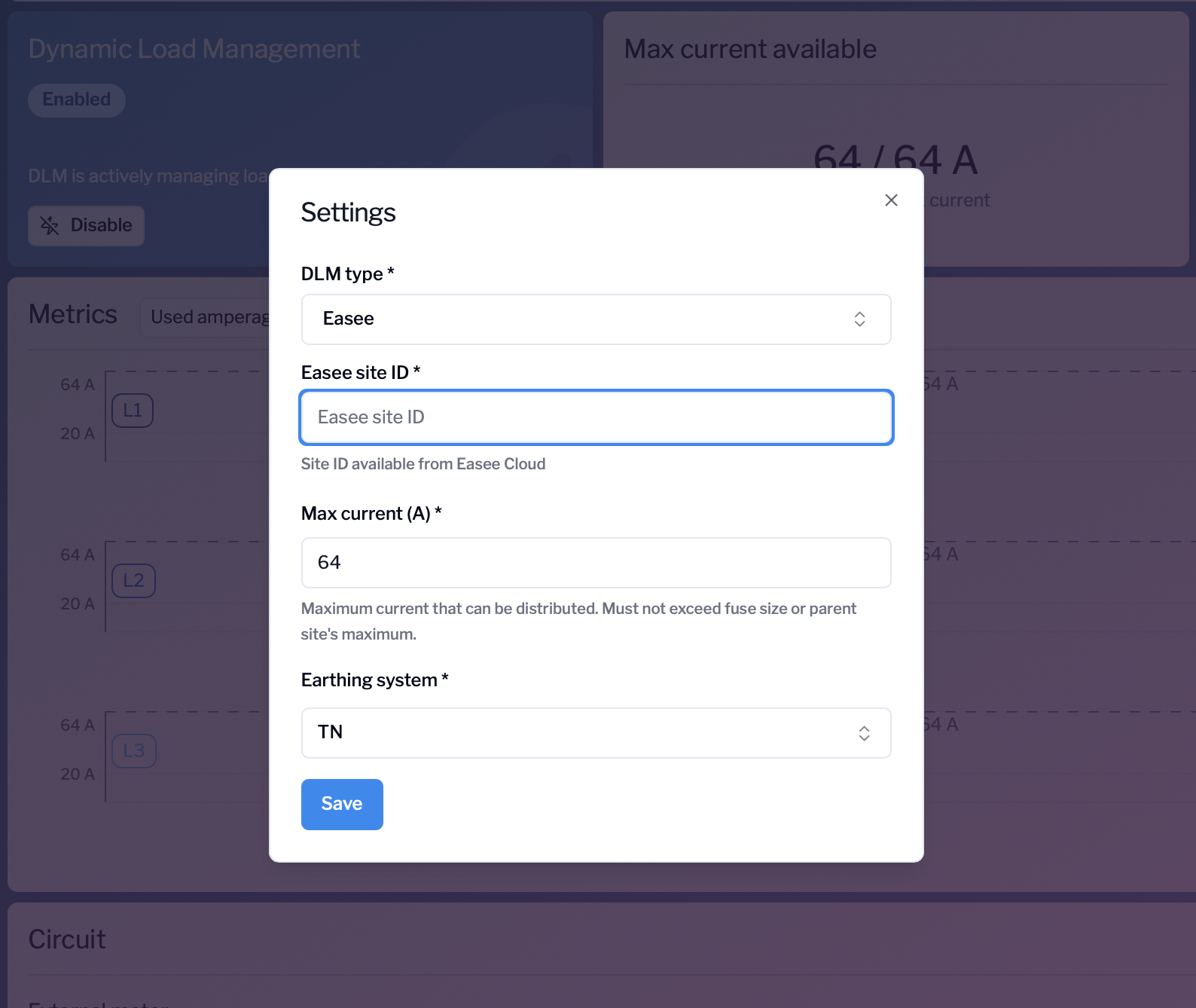
The management of Easee chargers is done at site level. To configure a site as Easee site DLM type needs to be set on Easee in the DLM Settings and the Easee site ID is required (this is the site id in the Easee cloud needed to refer to the same site through the Easee API). Max current and Earthing system can be set normally as done also for the OCPP sites.
Note that currently an Easee site can have only Easee chargers.
Profiles Ensure:
Charging profiles are crucial for maintaining safe, efficient, and flexible charging operations. The eMabler platform’s use of both OCPP and Easee profiles (for max current only) helps meet various operational and safety requirements. Key benefits include:
Safety Fallback During Disconnections:
Fallback Mechanism:
In the event of a disconnection, the system reverts to the Default Profile to ensure no current is flowing, reducing the risk of overcurrent situations or electrical faults.Purpose:
This provides a safety net, ensuring that even if there’s an issue with communication or connectivity, the system can safely terminate charging and prevent any unintended power flow. The Default Profile ensures chargers are only activated when they are safe to do so.
Throttling When Current Is Limited:
Throttling Functionality:
When the system detects that grid capacity is limited (e.g., due to external factors such as high electricity demand or other system constraints), the TxProfile can reduce the charging current delivered to EVs. This prevents overloading of the grid or local infrastructure and helps balance power usage across multiple stations.Purpose:
Throttling the current is essential for protecting infrastructure and ensuring sustainability. It helps optimize power distribution and ensures the grid can handle peak demand without interruptions, making the system more resilient.
Support for Multiple Connector Scenarios:
Multiple Connectors:
In environments where chargers have multiple connectors (e.g., public charging stations with several charging points), different profiles can be assigned to each connector based on its priority or operational needs. For instance, one charger may prioritize fleet vehicles, while another prioritizes public users.Purpose:
This capability ensures that each connector can be treated independently, enabling flexible management of power delivery across multiple charging stations and vehicles simultaneously. It enhances efficiency, convenience, and cost optimization by ensuring that each connector operates according to specific needs.
//Default profiles to the charger that are used if no Transaction profiles are received
//Charger will also drop to this profile if the transaction profile expires and there is no new TxProfile received
[2, “d4ffe52f-2b9a-4654-a1b6-968aecc7056e”,“SetChargingProfile”,{“connectorId”:0,“csChargingProfiles”:{“chargingProfileId”:787834106,“stackLevel”:0,“chargingProfilePurpose”:“TxDefaultProfile”,“chargingProfileKind”:“Recurring”,“recurrencyKind”:“Daily”,“chargingSchedule”:{“duration”:86400,“startSchedule”:“2024-11-28T00:00:00",“chargingRateUnit”:“A”,“chargingSchedulePeriod”:[{“startPeriod”:0,“limit”:0,“numberPhases”:3}]}}}]
[3,“d4ffe52f-2b9a-4654-a1b6-968aecc7056e”,{“status”:“Accepted”}]
//Transaction profile send by the backend to the charger when transaction has been started
[2, "731182b7-84f3-491a-8b66-82f4dfbd3f05","SetChargingProfile",{"connectorId":4,"csChargingProfiles":{"chargingProfileId":185698260,"stackLevel":0,"chargingProfilePurpose":"TxProfile","chargingProfileKind":"Absolute","chargingSchedule":{"duration":1320,"startSchedule":"2024-11-28T08:14:51.8297545Z","chargingRateUnit":"A","chargingSchedulePeriod":[{"startPeriod":0,"limit":32,"numberPhases":3}]}}}]
[3,"731182b7-84f3-491a-8b66-82f4dfbd3f05",{"status":"Accepted"}]
//Another Transaction profile but different socket on the charger
[2,"371a490e-745e-4d14-9fcb-ad125b1102f2","StartTransaction",{"connectorId":2,"idTag":"dd4feeb65863522bbebc","timestamp":"2024-11-28T08:16:56.837Z","meterStart":1603285}]
[3, "371a490e-745e-4d14-9fcb-ad125b1102f2",{"idTagInfo":{"expiryDate":"9999-12-31T23:59:59.9999999Z","parentIdTag":"-1","status":"Accepted"},"transactionId":2122738465}]
//MeterValue coming from the charger that will trigger DLM to change profile and send it to the charger
[2,"9c2cd412-beab-4f55-b48a-639c2d2baba2","MeterValues",{"connectorId":2,"transactionId":2122738465,"meterValue":[{"timestamp":"2024-11-28T08:17:02.000Z","sampledValue":[{"value":"1603285.6","context":"Sample.Periodic","format":"Raw","measurand":"Energy.Active.Import.Register","location":"Outlet","unit":"Wh"},{"value":"0.0","context":"Sample.Periodic","format":"Raw","measurand":"Current.Import","phase":"L1","location":"Outlet","unit":"A"},{"value":"0.0","context":"Sample.Periodic","format":"Raw","measurand":"Current.Import","phase":"L2","location":"Outlet","unit":"A"},{"value":"0.0","context":"Sample.Periodic","format":"Raw","measurand":"Current.Import","phase":"L3","location":"Outlet","unit":"A"},{"value":"0.0","context":"Sample.Periodic","format":"Raw","measurand":"Power.Active.Import","location":"Outlet","unit":"W"},{"value":"0","context":"Sample.Periodic","format":"Raw","measurand":"Voltage","phase":"L1","location":"Inlet","unit":"V"},{"value":"0","context":"Sample.Periodic","format":"Raw","measurand":"Voltage","phase":"L2","location":"Inlet","unit":"V"},{"value":"0","context":"Sample.Periodic","format":"Raw","measurand":"Voltage","phase":"L3","location":"Inlet","unit":"V"},{"value":"0.0","context":"Sample.Periodic","format":"Raw","measurand":"Current.Offered","location":"Outlet","unit":"A"}]}]}]
[3, "9c2cd412-beab-4f55-b48a-639c2d2baba2",{}]
[2, "483655b3-f0bb-4021-892d-f52051ecb1cb","SetChargingProfile",{"connectorId":2,"csChargingProfiles":{"chargingProfileId":28439086,"transactionId":2122738465,"stackLevel":0,"chargingProfilePurpose":"TxProfile","chargingProfileKind":"Absolute","chargingSchedule":{"duration":1320,"startSchedule":"2024-11-28T08:16:03.6206023Z","chargingRateUnit":"A","chargingSchedulePeriod":[{"startPeriod":0,"limit":15,"numberPhases":3}]}}}]
Edge Cases
External Meter Failure or Data Delay
Scenario: The external meter providing non-EV load data fails or sends delayed/incorrect readings.
Consideration: DLM might over-allocate current to chargers, risking fuse overload.
Mitigation (Guide-Specific):
Set Fuse Size correctly at the main site level.
Apply a safety margin when configuring MaxCurrent.
Validation Rule: Operators must set MaxCurrent ≤ 90–95% of FuseSize.
Example:
FuseSize = 250A
MaxCurrent = 225A (90%)
Meter fails → EffectiveMaxCurrent capped at 225A
Unexpected High Non-EV Loads
Scenario: A sudden elevator startup, HVAC surge, or lighting peak coincides with EV charging at full capacity.
Consideration: External loads are spiky and can momentarily exceed thresholds.
Mitigation (Guide-Specific):
Build safety margin into MaxCurrent (90–95% rule).
Dynamic response via EffectiveMaxCurrent:
EffectiveMaxCurrent=MaxCurrent−ExternalLoadEffectiveMaxCurrent = MaxCurrent - ExternalLoadEffectiveMaxCurrent=MaxCurrent−ExternalLoad
Validation Rule: EffectiveMaxCurrent must update in <1s.
Example:
FuseSize = 250A, MaxCurrent = 225A
Normal ExternalLoad = 40A → EffectiveMaxCurrent = 185A
Elevator starts, ExternalLoad = 100A → EffectiveMaxCurrent = 125A
DLM throttles EV sessions accordingly
DC Charger Ramp-Up Behaviour and 5A Headroom
Scenario: DC chargers take time to reach full authorised power.
Consideration: DLM risks wasting kW if it only matches measured values.
Mitigation (from eMabler):
Add +5A margin after conversion
Incremental increase logic:
If charger ramps successfully → continue 2 kW steps
If charger does not ramp → hold at current level
Formula Update:
Iauthorised=PauthorisedVRMS+5AI_{authorised} = \frac{P_{authorised}}{V_{RMS}} + 5AIauthorised=VRMSPauthorised+5A
Example:
Authorised = 20 kW, measured = 19.3 kW
DLM authorises 22 kW (+5A headroom)
Case 1: Measured = 22 kW → next step = 24 kW
Case 2: Measured = 19.3 kW → DLM holds at 22 kW
Responsibility and Limitations
The eMabler Dynamic Load Management (DLM) system provides tools and logic to prevent overloads and optimise charging. However, correct operation depends on accurate site configuration and proper use of external components.
Important: eMabler is not responsible for issues arising from:
Incorrect site configuration
Fuse Size not set according to the physical main fuse capacity
MaxCurrent configured without a safety margin
Wrong hierarchy mapping (site, subsite, group structure)
External meter faults or misconfiguration
Broken, delayed, or inaccurate meter signals
Incorrect meter ID, manufacturer settings, or wiring errors
External loads not connected to or measured by the configured meters
Operator errors or omissions
Failure to configure Offline Current fallback values
Incorrect Site Type selection (e.g., Easee vs OCPP)
Overriding safety recommendations in the configuration
Third-party hardware behaviour
Charger firmware limitations or non-compliance with OCPP/Easee specifications
Delays or faults in DC charger ramp-up beyond the defined +5A logic
Failures in non-EV infrastructure (e.g., HVAC, elevators, lighting)
Operator Responsibility:
Configure Fuse Size and MaxCurrent correctly (90–95% rule)
Ensure external meters are installed, calibrated, and maintained
Verify site hierarchy reflects the physical installation
Monitor alarms and notifications raised by the system
Disclaimer:
eMabler provides the DLM system as a software orchestration layer. While the system applies logic to prevent overloads, ultimate responsibility rests with the site operator or owner.